Design A Combinational Circuit For 4 Bit Binary Subtractor
4 Bit Binary Adder Subtractor Geeksforgeeks

Binary Subtractor Used For Binary Subtraction
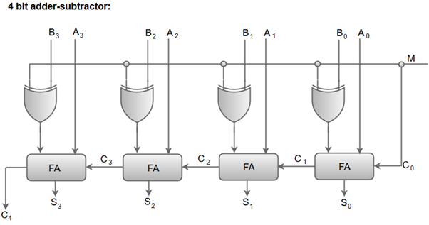
Binary Adder Subtractor Combinational Logic Circuits Electronics Tutorial
Solved Using Four Half Adders Design A Four Bit Combinat Chegg Com
Binary Adder And Subtractor
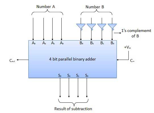
Parallel Adder And Parallel Subtractor Geeksforgeeks

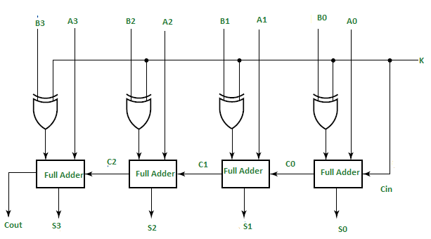
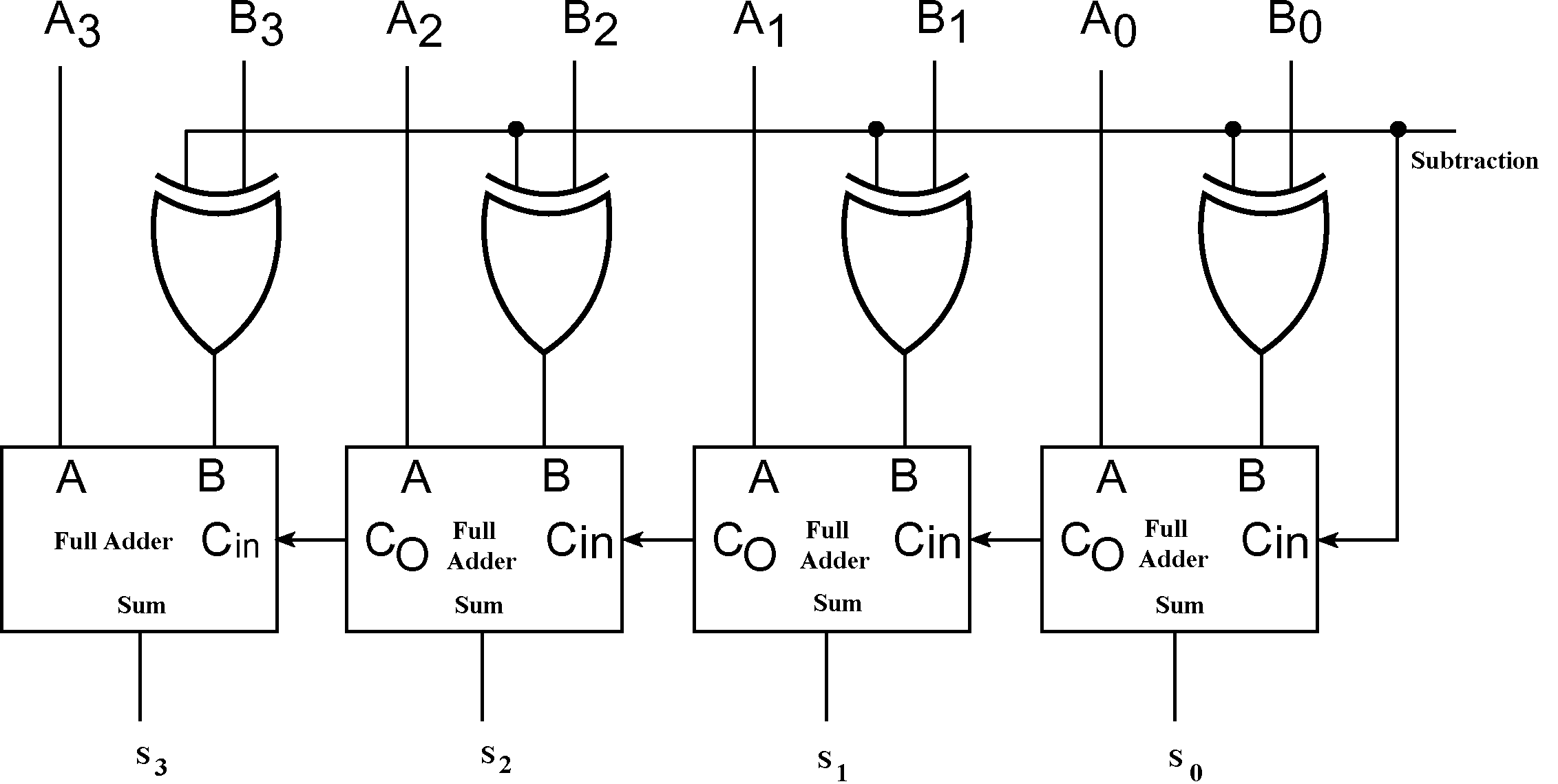
The control input is controls the addition or subtraction operation.
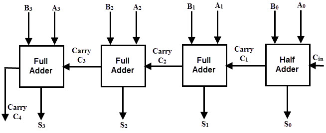
Design a combinational circuit for 4 bit binary subtractor.
Combinational Circuits Tutorialspoint
Digital Arithmetic Circuits Tutorialspoint

Binary Adder And Binary Addition Using Ex Or Gates
Coa Binary Adder Subtractor Javatpoint

Chapter 4 Homework V3 Solutions Ens 221 Csi Studocu
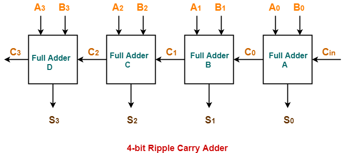
Ripple Carry Adder 4 Bit Ripple Carry Adder Gate Vidyalay
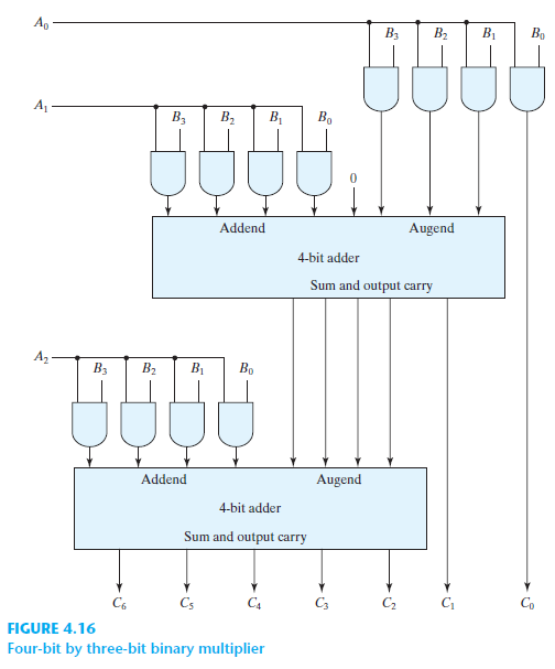
Solved For A Binary Multiplier That Multiplies Two Unsigned Fo Chegg Com

Cs201 Design Adders Lab

Q 4 11 Using Four Half Adders Hdl See Problem 4 54 A Design A Full Subtractor Circuit Incremen Youtube
4 10 Design A Four Bit Combinational Circuit 2 S Complementer The Output Generates The 2 S Youtube

What Is The Logic Diagram Of 4 Bit Subtractor Quora
Morris Mano Edition 3 Exercise 5 Question 3 Page No 197 Gate Overflow
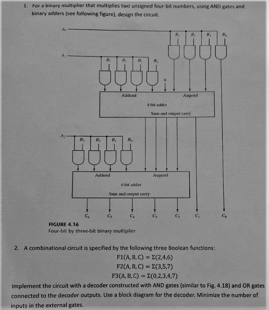
Solved 1 For A Binary Multiplier That Multiplies Two Uns Chegg Com

Solved Using Four Half Adders A Design A Four Bit Combinational Circuit Incrementer A Circuit That Adds I To A Four Bit Binary Number B Design A Four Bit Combinational Circuit Decrementer A Circui Study Com
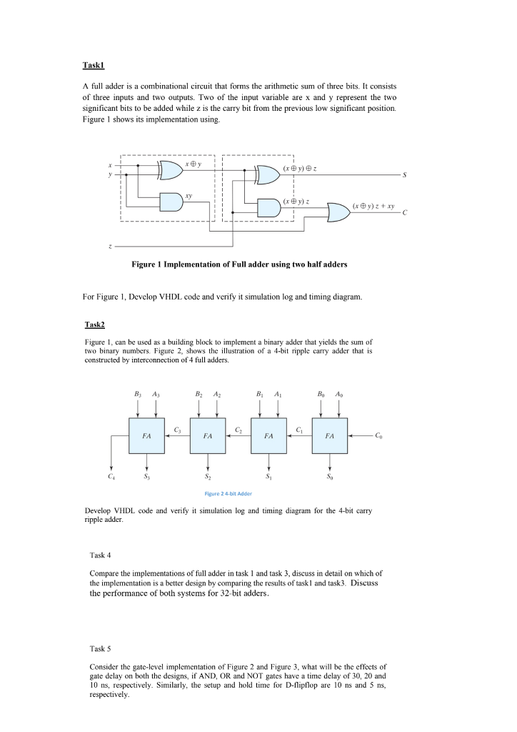
A Full Adder Is A Combinational Circuit That Forms Chegg Com
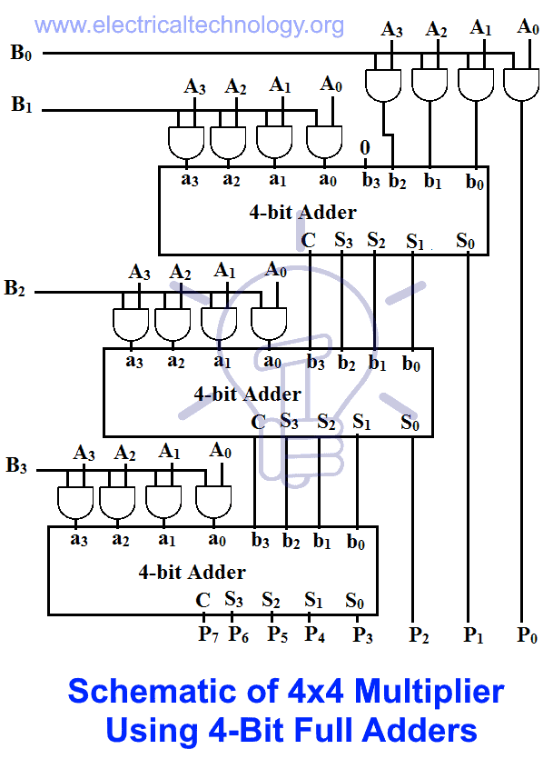
Binary Multiplier Types Binary Multiplication Calculator
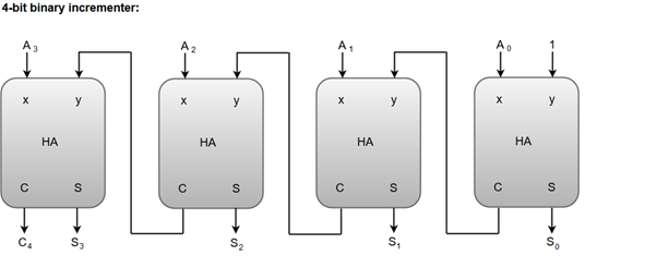
Coa Binary Incrementer Javatpoint

Digital Comparator And Magnitude Comparator Tutorial
Https Encrypted Tbn0 Gstatic Com Images Q Tbn 3aand9gcrn2yx7cfvaroymkhkj5v Xuvnnnusrpfzrpx1eccmvyszzau9m Usqp Cau
Source : pinterest.com
